


Ch. 5 Project
이 글은 insight 출판사의 [밑바닥부터 만드는 컴퓨팅 시스템 / The Elements of Computing System]이라는 책에 있는 프로젝트(과제)를 수행하는 글입니다.
해외에서는 nand2tetris라는 이름의 프로젝트로 알려져 있습니다! 동일한 내용으로 구성되어 있으니, nand2tetris를 공부할 때 참고바랍니다.
Chapter 5. 컴퓨터 아키텍처 - Project
Chapter 5의 프로젝트에서는 최소한의 구성으로 만든 간단한 Computer를 HDL로 작성하여 구현한 뒤, ROM에 예제 프로그램을 올려 직접 실행까지 시켜본다.
HDL을 통해 구현할 컴퓨터의 대략적인 구조는 아래와 같다. 여기에서 Instruction Memory(ROM)은 주어진 Chip을 활용하며, 우리는 CPU와 Data Memory, Computer를 HDL을 이용해 구현해볼 것이다.
CPU.hdl
Cpu는 앞서 이론 글에서 작성하였던 것처럼 아래의 도표의 회로를 갖는다.

위 그림을 HDL로 옮기면 아래와 같은 코드가 나온다. CPU chip의 instruction input을 따라 흐름 순서대로 구현할 예정에며, 주석을 통해 더 자세히 설명해보겠다.
CHIP CPU {
	IN inM[16], instruction[16], reset;
	// instruction은 "ixxa cccc ccdd djjj" 의 bit 배열을 갖는다. 제일 오른쪽이 index 0이다.

	OUT outM[16], writeM, addressM[15], pc[15];


	PARTS:
	// A register
	// if instruction[15](i bit) is 0 ,then A instruction, else C instruction
	// A instruction 인지 C instruction인지 확인 후 aType, cType을 set 한다.
	Not(in=instruction[15], out=aType);
	Not(in=aType, out=cType);

	// C instruction일 때 dest0 bit이 1이면 ALU의 result가, 0이면 instruction이 A register에 input된다.
	And(a=cType, b=instruction[5], out=ALUtoA);
	Mux16(a=instruction, b=ALUout, sel=ALUtoA, out=ARegin);

	// instruction이 A type이거나 dest0이 1이면 (A Register에 값을 저장해야하면) loadA가 1이 되어, A register에 input된 값이 저장된다.
	// 값이 input되더라도 load bit이 set되어야 저장된다는게 헷갈릴 수 있다.
	Or(a=instruction[5], b=aType, out=loadA);
	ARegister(in=ARegin, load=loadA, out=ARegout);


	// ALU의 Y input에 A register의 값이 들어갈 지 inM이 들어갈 지 instruction의 a bit이 결정한다.
	// instruction's 'a bit' select which will be input between A & M
	Mux16(a=ARegout, b=inM, sel=instruction[12], out=ALUYin);


	// D register
	// instruction이 C type이고 dest1이 1이면 (D register에 값을 저장해야하면) loadD가 1이 되어, D register에 ALUout이 저장된다.
	// if C instruction and instruction[4] is 1 , then ALUout
	And(a=cType, b=instruction[4], out=loadD);
	DRegister(in=ALUout, load=loadD, out=DRegout);


	// ALU
	// ALU에는 input 2개, 6개의 comp bit, ng, zr, ALUout을 연결해준다. 앞에서 만들었던 ALU chip을 활용한다.
	ALU(x=DRegout, y=ALUYin, zx=instruction[11], nx=instruction[10], zy=instruction[9], ny=instruction[8] , f=instruction[7], no=instruction[6] , out=ALUout, zr=ZRout, ng=NGout);


	// Jump
	// Jump conditions - Negative, Zero, Positive
	// ALU의 연산 결과로 나온 ng, zr flag를 이용해 pos flag도 만들어둔다.
	Or(a=NGout, b=ZRout, out=NGZR);
	Not(in=NGZR, out=posi);

	// instruction의 3개의 jump bit과 해당 조건을 비교하여 옳은게 있으면 jlt, jeq, jgt에 1을 set한다.
	And(a=instruction[2], b=NGout, out=jlt);
	And(a=instruction[1], b=ZRout, out=jeq);
	And(a=instruction[0], b=posi, out=jgt);

	// if true exist between three conditions, jump
	// instruction이 C type일 때 위 조건 중 하나라도 1이 있으면 (하나라도 조건을 충족했다면 - 범위에 들었다면) jump를 실행한다.
	Or(a=jlt, b=jeq, out=jle);
	Or(a=jle, b=jgt, out=jumpToA);
	And(a=cType, b=jumpToA, out=PCload);
	Not(in=PCload, out=PCinc);


	// PC
	// PC에는 A Register에 저장되어있던 값을 load하여 jump를 실행한다.
	// jump가 없을때는 단순히 inc bit을 set하여 PC값을 증가시킨다.
	PC(in=ARegout, inc=PCinc, load=PCload, reset=reset, out[0..14]=pc);


	// CPU Outputs
	// if destination is Memory and cType, writeM = 1
	And(a=cType, b=instruction[3], out=writeM);
	Or16(a=false, b=ARegout, out[0..14]=addressM);
	Or16(a=false, b=ALUout, out=outM);
}
Memory.hdl
메모리는 다음과 같은 그림의 input과 output을 갖는다.

위 그림에서 input address는 15bit!!!
이를 앞의 프로젝트에서 만들었던 HDL Chip들을 이용해 구현하면 다음과 같은 코드를 얻을 수 있다.
CHIP Memory {
	In in[16], load, address[15];
	Out out[16];

	PARTS:
	// address의 13, 14 bit을 통해 In 값을 어디에 load 해야할 지 결정
	DMux4Way(in=load, sel=address[13..14], a=loadram1, b=loadram2, c=loadscreen, d=loadkbd);
	// 0x0000~0x1FFF, 0x2000~0x3FFF는 같은 RAM 주소 → 통합
	Or(a=loadram1, b=loadram2, out=loadram);

	//각 영역에서 out 값을 ramout, scrout, kbdout으로 지정.
	RAM16K(in=in, load=loadram, address=address[0..13], out=ramout);
	Screen(in=in, load=loadscreen, address=address[0..12], out=scrout);
	Keyboard(out=kbdout);  // kbd는 input 신경쓰지 않는다.

	// ramout, scrout, kbdout 중 address의 13, 14 bit을 통해 원하는 out값만 반환
	Mux4Way16(a=ramout, b=ramout, c=scrout, d=kbdout, sel=address[13..14], out=out);
}
Computer.hdl
위에서 만든 hdl 파일들을 조합하여 computer를 구현할 수 있다. 이는 매우 기초적인 수준의 컴퓨터이지만, 현대의 컴퓨터 기본구조인 폰 노이만 구조와 동일하다.

CHIP Computer {
	In reset;

	PARTS:
	// ROM은 원래 구현된 Chip을 이용
	ROM32K(address=pc, out=instruction);

	CPU(inM=memOut, instruction=instruction, reset=reset, writeM=writeM, outM=outM, addressM=addressM, pc=pc);
	Memory(in=outM, address=addressM, load=writeM, out=memOut);
}
이렇게 구현해둔 뒤 제공된 하드웨어 시뮬레이터로 Computer.hdl을 테스트하면, ROM에 올린 프로그램이 정상적으로 작동하는 것을 확인할 수 있다.
프로젝트 예시
Add.hack
Add.hack 프로그램은 메모리[0]=메모리[2]+메모리[3] 이라는 연산을 수행한다. HW 시뮬레이터 위에 우리가 앞서 만든 Computer.hdl 파일을 로드하고, 우측 하단의 ROM에 Add.hack 프로그램을 올려 실행시킬 수 있다.
프로그램의 실행을 위해 메모리에 미리 1, 2, 3, 4 라는 값을 순차적으로 넣어주었다.
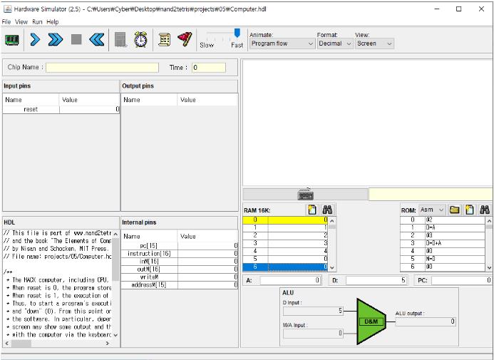
위 상태에서 실행을 하면 아래와 같은 결과를 얻을 수 있다.

Max.hack
이 프로그램은 메모리[0], 메모리[1] 중 더 큰 값을 메모리[2]에 저장하는 작업을 수행하는 프로그램이다. HW 시뮬레이터 위에 Computer.hdl을 올리고, ROM에 Max.hack 프로그램을 올려 실행하면 된다.
이를 검사하기 위해 미리 메모리[0]=7, 메모리[1]=10 을 해두었다.
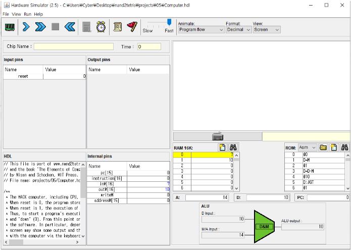
위 상태에서 실행시키면 아래와 같은 결과를 얻을 수 있다.

'학부생 CS > Elements of Comp-Sys' 카테고리의 다른 글
| The Elements of Computing System - Ch.6 PJ (1) (0) | 2020.11.22 |
|---|---|
| The Elements of Computing System - Ch.4 PJ (0) | 2020.08.30 |
| The Elements of Computing System - Ch.3 PJ (0) | 2020.08.23 |
| The Elements of Computing System - Ch.2 PJ (0) | 2020.08.02 |
| The Elements of Computing System - Ch.1 PJ (0) | 2020.07.26 |